I built ( or assembled if you must) the PAC 12 portable antenna to take on a trip to Texas this past May. Pacific Antenna who make the kit, produce a fine product at a reasonable price. The kit consists of several pieces of aluminum rod threaded for 1/4-20 SAE along with several feet of 18AWG magnet wire for two coils and the forms. A more complete description can be found at
Pacific Antenna Site . My kit went together well or so it seemed. I did not have time to thoroughly test the antenna once it was made before I left on my trip. The result was poor performance in the hill country of Texas.
Once back home I experienced the same lack of performance. Turns on the 40Meter coil were recounted and the whole thing reviewed. The antenna on an analyzer would tune to about a 1.1 to 1 SWR at the bottom of the 40 meter band. It behaved exactly as the designer explained howerer I could not get out on the darn thing.
I know that as a shortened radiator, performance would not be as robust as my Center Fed Zepp or even my quarter wave vertical. I was also working with 5 or 6 watts at most. so told myself to keep expectations real. One of the local elmers lent me a TV twin lead counterpoise to try out. That did not help. At this point I posted on the Pacific antenna yahoo group. The response while not helpful, at least got me to thinking about the problem. How can all of these antennas work and not mine?

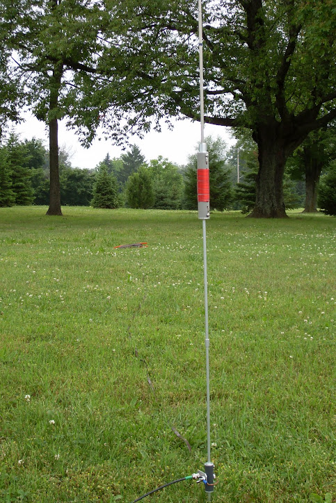
Back to the elmer's house for more discussion. While listening to him talk with another local ham about his mobile antenna mount he said something that got me thinking. He said, "remember you are not just dealing with a DC circuit with the antenna but an RF circuit." This got me to thinking. Suppose my problem was at the feed point. In my haste to get the antenna ready for travel, I soldered the wires in the kit to the BNC connector and then to the screw tabs. I left the wires the length I was given and let the wires cross. Again DC thinking, they are insulated so no issue! The picture shows just about how I had the wires from the BNC connector going to the points on the antenna. Well wrong.
I resoldered the wires to make them not only shorter, but also so they are separated as much as possible.
The reward was my first contact with the K1 and the Pac12 with N0FKC Pete in Minnesota. Pete gave me a 579 signal report just before it clouded up for rain. Thank you Pete for hanging in there with my experiments. The lesson here is that one has to think like RF in working with Antennas not just DC!